Environmental Protection Magazine
 Groundwater Monitoring Gets a Direct Push!
| View main article | View article references |
PICTURES & DRAWINGS
Figure 2: Driller and helper stripping and shoveling waste drill cuttings during monitoring well installation. Handling and proper disposal of contaminated cuttings may consume up to 50% of the field investigation budget. Waste cuttings also present a significant health and safety hazard when contaminated. Refer back to article.
 Figure 3: Probe operators installing a monitoring well using direct push methods. Note, little if any cuttings are generated. The small diameter grout tube is visible just left of center in the photo. Bottom-up grouting with 25% solids bentonite slurries or neat cement grout provides high integrity well construction. Refer back to article.
 Figure 4: Schematic of a direct-push groundwater sampling device. Temporary installation for sample collection and abandonment grouting may require less than one hour. The tools are decontaminated for multiple re-use. Refer back to article.
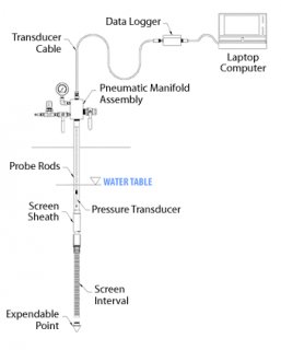
Figure 5: Schematic of DP installed small diameter monitoring well construction. The primary difference between conventional well design and the DP well design is the smaller diameter. The New ASTM Standard Practice D 6725 details the procedure for direct push installation of the small prepacked screen monitoring wells. Refer back to article.
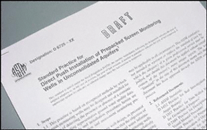
Figure 6: New ASTM Standard Practice D 6725 details the procedures for installing prepacked screen monitoring wells with direct push methods. This new Standard is scheduled for publication by ASTM this summer. Refer back to article.
7A.
7B.
7C.
Figure 8: Direct push methods can be combined with pneumatic slug testing to determine formation hydraulic conductivity in DP monitoring wells or temporary groundwater sampling devices. Refer back to article.


